
Introduction
Site list (GPS fixes) Walks (GPS tracks) Video clips Panoramas
Electronic projects:
Bat detector
Lamp tests
µ-controlled lamp
SEPIC-based lamp
ISP isolators
Making SMT boards
Expedition logs:
Spain 1973, 1974,
1975, 1976, 1977,
1979, 1982, 1983,
1985, 1986, 1987,
1988, 1989, 2000,
2001, 2002, 2003,
2004, 2005, 2006,
2007, 2008, 2009,
2010, 2011, 2012,
2013, 2014, 2015,
2016, 2017, 2018,
2019, 2020, 2021,
2022, 2023
Mexico
New England
Translation:
AVR STK500 ISP isolator circuits
While developing a circuit for driving high-power LEDs, using the Atmel » AVR RISC ATTiny15L microcontroller », we discovered a flaw in the AVR STK500 starter kit; the three lines providing in-system programming (ISP) are permanently connected to the microcontroller (PB0 through PB1 on the ATTiny15).
The connections to these lines have an impedance of about 1KΩ, which makes even simple switch and LED circuits difficult to use on the ports, and makes analogue processing essentially impossible.
Fortunately there is a simple work-around which does not require modifying the STK500 board. A hex non-inverting tri-state buffer (or any similar device with at least three buffers) can be used to disconnect the three lines when the RESET line is not low. When the RESET line is pulled down for programming, the three lines are connected and can function as usual.
The buffer can be built on a PCB or small piece of stripboard and included in a 6-way cable which replaces the usual jumper cable between ISP6PIN and (in our case) SPROG1.
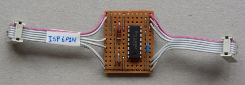
Here’s how our prototype, built on stripboard, looks:
In the picture, the six-way plug on the left connects to ISP6PIN; the other connects to the chosen PROG port. The IC is a MC14503B CMOS part, as shown in the schematic (PDF) for the prototype. The schematic is laid out for direct transfer to stripboard, with the strips running horizontally (the only break other than the eight strips under the IC is in the top strip between MISO out and MISO in).
The two resistors protect the two outputs from accidental shorts (for example, if one of the pins is connected to ground through a switch), and the capacitor provides decoupling.
If constructed as shown, pin 1 of the two connectors is at the top (connected to the coloured wire). The board is then inverted when plugged in, which keeps the copper side away from the headers on the STK500.
If desired, the RESET line itself can be isolated by making a break in the appropriate strip and adding a wire link and a third resistor to IN4 and OUT4 of the hex buffer. The RESET jumper on the board will then need to be removed and an appropriate pullup set for PB5. ADC0 can then be used to measure voltages between Vcc and 0.6Vcc (lower voltages would prevent the microcontroller exiting reset state, unless reset is disabled).
SMT AVR STK500 ISP isolator circuit
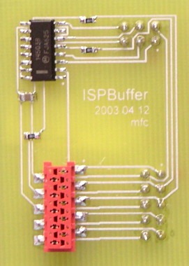
Here’s the latest, Surface Mount Technology, (SMT) version of the isolator circuit:
This board also acts as an adapter between the pin-header connectors of the STK 500 starter kit and the lower-profile connectors we chose for SMT development. The pin-header 6-way connector is on the obverse (non-copper) side of the board at top right.
The hex buffer is seen at the top left, with its decoupling capacitor and three 470Ω output resistors (RESET is also isolated in this circuit).
The primary output of the board is the AMP Micromatch 10-way connector at the bottom left, and these ten signals are also connected to a 10-way pin-header block on the obverse at the bottom right (this block allows easy access to the signals for testing and also allows the board to be used as an alternative to the prototype above for bread-boarding, etc.). If not required, either of the output connectors can be omitted.
Pins 1-6 on the 10-way connectors carry the same signals as the same pins on the Atmel ISP-6PIN connector on the STK 500. The other four pins are available for application-dependent connections.
Here are images of the board layout and the schematic for the SMT version.
Please note: if you build either of these circuits, you do so at your own risk.

